
A latch is a one-bit memory element. Unlike a combinational gate, its output can depend on a value stored earlier. A latch is level-sensitive: while its enable level is active, the latch is transparent and its output can follow its input. When the enable becomes inactive, it holds the last value.
How cross-coupled gates hold a bit
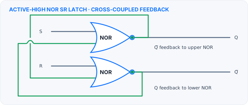
The SR latch
An SR latch has Set (S) and Reset (R) controls with outputs Q and Q̄. In a NOR-based active-high latch, S=1,R=0 sets Q to 1; S=0,R=1 resets Q to 0; and S=0,R=0 holds the previous state. The pair S=R=1 is invalid in this implementation because it forces both outputs low. NAND-based SR latches use active-low controls, so always check the gate type and signal polarity.
The D latch
A D latch adds a data input and an enable. When enable is active, D can propagate to Q. When enable is inactive, feedback keeps the stored value. Internally, D and its complement generate the set and reset behavior, avoiding the forbidden SR input combination.
Transparency and timing
“Transparent” means changes at D may propagate to Q during the active enable level. If multiple latches are open together, a change can travel through more than one stage in the same time window; this is called race-through. Designers control enable phases and timing so data moves through the intended stages.
Latch versus flip-flop: the key difference
A latch is level-sensitive: it can follow its input for the whole time its enable is active. A flip-flop is edge-triggered: it captures its input at a clock transition and holds that value between edges.
| Feature | Latch | Flip-flop |
|---|---|---|
| Sensitivity | Level-sensitive | Edge-triggered |
| Control signal | Enable or gate level | Clock edge |
| When input can affect output | Throughout the active enable level | At the active edge, subject to setup and hold time |
| Behavior between events | Holds while disabled | Holds between active clock edges |
| Common use | Enable-controlled storage and latch pipelines | Registers, counters, and synchronous state machines |
A master–slave flip-flop is commonly built from two latches driven by opposite clock phases. The complete pair behaves as an edge-triggered element even though each internal storage stage is a level-sensitive latch. This is why the terms are related but not interchangeable.
Where latches are used
Latches appear in level-sensitive pipelines, temporary storage, control logic, and as building blocks for some master–slave flip-flops. A master–slave arrangement uses two latches with opposite enable phases: one accepts data while the other holds, then their roles switch. This prevents data from flowing continuously through both stages.
Study tip: first identify whether the latch is active-high or active-low. Then determine what happens while enabled and what value is held while disabled. This avoids many latch truth-table mistakes.