
A flip-flop stores one bit and updates its state at a specified clock edge, commonly the rising edge. Write the current output as Q(t) and the value after the active edge as Q(t+1) or Q⁺. Between active edges, the stored state remains stable, subject to setup and hold timing requirements.
Clocked storage and JK feedback
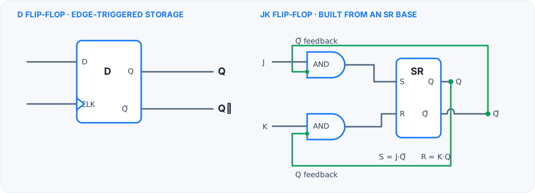
S=J·Q̅ and R=K·Q; the feedback makes J=K=1 toggle the stored state.SR flip-flop
The SR flip-flop provides Set and Reset controls. In the common active-high behavior, S=1,R=0 sets Q, S=0,R=1 resets Q, and S=0,R=0 holds. Simultaneously asserting set and reset is invalid for the basic implementation. The clock determines when an input request can update the state.
D flip-flop
The D flip-flop has one data input and the simple next-state equation Q⁺ = D at the active edge. It captures a snapshot of D and holds that value until the next edge. D flip-flops are common in registers, pipelines, and state registers.
JK flip-flop
The JK flip-flop defines the case where both controls are 1. Its characteristic equation is Q⁺ = JQ̄ + K̄Q. Thus J=0,K=0 holds, J=1,K=0 sets, J=0,K=1 resets, and J=1,K=1 toggles the current state. Substituting each J,K pair into the equation verifies the behavior.
T flip-flop
The T flip-flop toggles when T=1 and holds when T=0. Its equation is Q⁺ = T ⊕ Q. With T tied high, Q changes on every active clock edge, so the output frequency is half the clock frequency.
Setup, hold, and propagation delay
Input data must be stable for a minimum setup interval before the active edge and a minimum hold interval after it. Violating either requirement can cause an incorrect capture or metastability, where the output takes an unpredictable time to settle. Clock-to-Q delay describes how long after the edge the new output becomes valid.
A method for solving state questions
- Record the current state before the edge.
- Read the input values at the active edge.
- Apply the flip-flop characteristic rule to find Q⁺.
- Use Q⁺ as the current state for the next clock step.
The equation describes the value captured at an edge; the flip-flop does not continuously copy the next-state equation to its output.